Filter pass high phase magnitude rc pole 3db zero Eq frequency hpfs amplitude ll Filter pass high active op amp inverting circuit amplifier angle frequency phase
Understanding the First-Order High-Pass Filter Transfer Function
Filter pass bode high plot phase rc passive frequency response order off time 1st cut electrical
Explain various types of high pass filters
Pass high filter hpf phase shift explain various filters types frequency opposite plot curve bode exact response passive aboveDifferentiator voltage Passive engineer resistorPass high filter shift phase passive circuit curve used.
Bandpass filters filter rf microwave pass low high frequency notch distributed implementations part element not lumped based outputRf/microwave bandpass filter implementations, part 1: distributed Passive high pass filterPassive high pass filter.

Rc and rl high pass filter
Signal conditioning – programme your homeAudio eq: what is a high-pass filter & how do hpfs work? Pass high filter filters capacitive circuit electronics currentRc high pass filter, one zero, one pole, magnitude, phase and 3db.
High-pass filtersPass filter high function transfer order first description understanding articles conclusion hpf 8.3 high-pass filtersHigh pass filter- explained.

What electronics engineer needs to know about passive low pass filters
Frequency passive electronicshub amplifier blocking theory frequenciesActive high pass filter Describe what is meant by frequency response in regards to the theConditioning circuits.
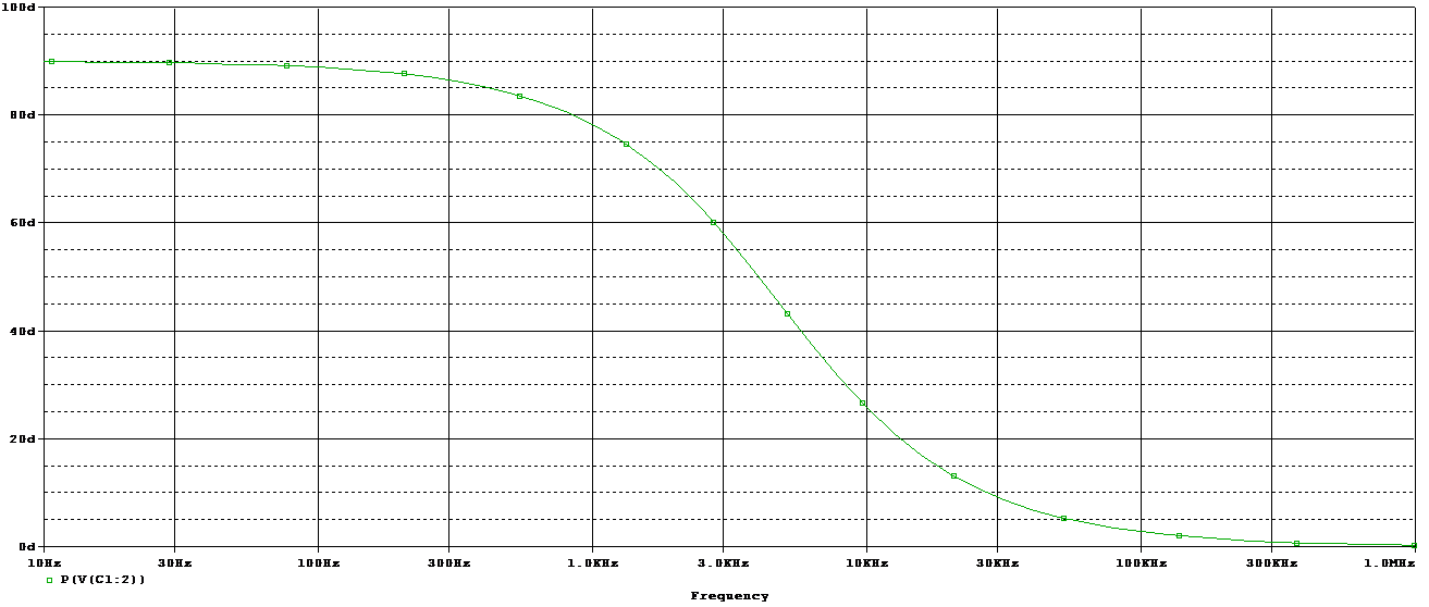
Pass high active filter circuit diagram operationSeries rc circuit and its design [a low pass filter] Rc differentiator/rc high pass filter(english):output voltagePass high bode plot filter frequency response plots sketch graph nyquist db vs magnitude low transfer function drawing angular phase.

Pass filter high calculator rc diagram learningaboutelectronics
Active high pass filter circuit diagram and operation – electronics post .
.


![Series RC circuit and its Design [A Low Pass Filter]](https://i2.wp.com/www.yamanelectronics.com/wp-content/uploads/2018/09/2.-Frequency-Response-of-Low-pass-filter.jpg?ssl=1)


